How to draw lines in Autocad for beginner

How to draw lines in Autocad for beginner


How to draw lines in Autocad for beginner


To practice this Basic AutoCAD tutorial, you can use any version of Autocad, because this line drawing is included in the basic autocad functions. From the initial version of Autocad to version 2020, the command or command remains the same.

How to draw free lines

  1. AT Type of line or l command, then enter.
  2. On the Autocad drawing screen, left click anywhere you want.
  3. Move the cursor using the mouse to the right, to the left, up, down or wherever I want it yet on the drawing screen. Then click on the left again.
  4. If you still want to continue creating the line, point to the cursor again wherever you want. Then click on the left again.
  5. To finish the line, press the exhaust key on the keyboard. Then, the AutoCAD drawing screen will form a recently created free line drawing.


How to draw free lines of a certain length

  1. AT Type of line or l command, then enter.
  2. On the Autocad drawing screen, left click anywhere you want.
  3. Move the cursor to another part of the AutoCAD drawing screen, then write a certain length (for example, 10), then enter.
  4. To finish how to draw free lines, you can press the exhaust key on the keyboard or press enter.


How to draw a line using coordinates

  • AT Type of line or l command, then enter.
  • In the command, write the coordinates of the first point. For example, income 635354,1880066 and then income.
  • 3. In the command, write the coordinates of the second point. For example, income 635402,1880077 and then income.
  • If there is a third coordinate point, etc., take the third step again. If not, press the Enter or Exhaust key on the keyboard to finish the creation of the line.
  • If the drawing is not visible in the middle of the autocad screen, then in the type of Z command, enter, write E and then enter.
  • To add a reference on how to draw in AutoCAD using coordinate data, also read how to draw a field using coordinates

How to draw a line to connect two specific points

When drawing in Autocad, we sometimes want to draw an existing 2 points. To get an example, see the image below. I want to draw a line from point 1 to 4 and point 2 to 3.

Before taking the steps below, make sure the Snap mode for the end point is active so that, when left, the point can be necessary. How: Click the Tools Menu> Writing Settings ...> Click the Object Snap tab> Make sure the final point box is marked> Click OK.

Steps to make the line:
1. AT Type of line or l command, then enter.
2. Click on the end of the first point plane.
3. Click on the end of the fourth point of point.
4. Press the exhaust key on the keyboard to finish line creation.
5. Repeat step 1 to step 4 up to make a line from point 2 to point 3.


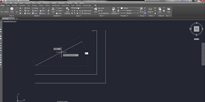
How to create a line with a specific angle and length

1. AT Type of line or l command, then enter.

2. On the Autocad drawing screen, left click anywhere you want.

3. Move the cursor to the upper right of the point made in step 2 until the angle is as large as we want (for example, 45 degrees), then write a certain length (for example, 30), then enter. To be clearer, see the image below.

4. Press enter or escape to finish the drawing of the line.


How to draw a line with coordinates, azimuth and a specific length (polar coordinates)

To put this tutorial into practice, let's use the sample data below:

Coordinate point A = 635400,1785100
AB length = 100 meters
Azimut ab = 60d50'10 "
The first step to create a line from the previous data is to establish the drawing units and management control, how:

1. Click the Format menu. Then select units or you can also write units in the command.

2. In the Drawing Units dialog box, make the following configuration.

In the length section. Write select decimal and precision Select 0.00

In the angle section. Write Select Deg/Min/Se | Precision Select 0D00'00 ”| Make sure the box is marked.
On the insertion scale, select meters.

Click the Instructions button. In the steering control dialog box, in the base angle section, select to the north. Then click OK.

Click OK to finish the configuration of drawing units.
The results of
Read more ...

How to Print AutoCAD in Layout According to Scale and Without Frames or Copy

How to Print AutoCAD in Layout According to Scale and Without Frames or Copy


How to print in Autocad in the design according to the scale and without frames or the copy

1. Prepare the image that will be printed on the model.

2. Verify or specify the unit used in the model drawing. The trick in the command can write the units command and then enter. In the Drawing Units dialog, section insertion scale, see or select the unit that will be used. For example, use meters.

Note: You can choose the unit, the important thing is to know what unit you choose because it will affect the value of the print scale.

3. Click the Layout1 or Layout2 tab. Click on the box line that has an image or you can also press Ctrl + A on the keyboard. Then press the delete key on the keyboard.

4. Right click on the active design tab. Select the page configuration administrator. For clarity, see the following image.

5. In the page configuration setting dialog box, click on the Modify button.

6. In the page configuration dialog box, make the following configuration.

In the Printer/Platterter section, select the name of the printer that will be used. If you don't know what a printer use, you can first select DWF6 ELLOT.
In the paper size section, select a paper size. For my example, I chose ISO expanding A3 (297.00 x 420.00 mm).

In the section of the plot scale, select mm and filling unit 1.
In the drawing orientation section, select a paper orientation. For the example, I chose the landscape option.
For the rest, leave it as it is and the results of the configuration I do, seem the image below.

If set as shown above, you can click OK.
7. In the page configuration setting dialog box, click on the Close button.

8. For how to create a graphic window in the design of Autocad, in the command write the MV command and then enter. Or if you are using a classic work space, you can also click on the view menu> Views> 1 viewport.

9. Draw a box how to make a rectangle within the design of the dotted line according to the desired size. Or if you want the picture to be as great as the paper, in the command you can also write Fit and then enter.

10. To adjust the scale, double click on the box that has been created.

Note: If the image does not appear in the middle of the picture, in the type of Z -Enter> E> Enter command.
11. Click the view scale to select the scale to be used. Location of the view scale See the red box in the image below. And for the example I choose 1: 100

Grades:
The 1: 100 scale is the view scale. Not the real scale on the ground.
To find out the real scale, the paper distance unit must be compared to the model of model image distance (paper unit: model drawing unit).
For example, the paper unit that uses is mm (step number 6) and the drawing unit of the model I use is meters (step number 2).
Then, when I select the scale of the 1: 100 graphic window, it means 1 mm: 100 m or if the unit is 1 mm: 100000 mm (1 m = 1000 mm). This is the true scale of 1: 100,000.
12. To finish the scale, double click outside the box.
13. To print or print a ready -to -design image, you can click on the File Menu> Draw or press the Ctrl+P keys on the keyboard.

14. In the plot dialog box, you must establish only the name of the printer that will be used for printing. But if step number 6 has been carried out, there is no need. Then you can click on the Preview button to see a general description of the printing results that will be obtained.

15. If the results agree with the desired image, right click. Select graphics.
If it does not match, right click, select leave. Or you can also press the exhaust key on the keyboard. Then, make changes in the configuration in the Plot dialog box as you want. This is how to establish the design of Autocad and how to print AutoCAD to fit the scale.

How to print in AutoCAD in design with frames and scale

1. Perform steps 1 to 7 How to print AutoCAD in the design according to the scale and without frame or headed above.

2. Create Marcos in the design in several ways. You can design from scratch, copy from drawings of the model, insert frames in the form of blocks and copy from ready design drawings.
For example, I will copy the framework from the default value
Read more ...

How to print autocad in layout without scale and frame arrangement


How to print autocad in layout without scale and frame arrangement

1. Prepare the image or map that will be printed on the model. For example I will print a map like the image below.

2. Click the layout1 tab or layout2. For my example, click the Layout1 tab and it looks like the following image.

Note: If you want to delete the Grid row display, don't delete it because the image will also be deleted. But in control of the layer deadly or freezing the icon frame. To make it clearer, see the red box in the following picture.

3. Click the File menu> plot or press Ctrl+P on the keyboard.
4. In the plot dialog box, make the following settings.

In the printer/plotter section, select the name of the printer to be used. For example I chose the Canon IP2700 series.

In the paper size, select the paper size. For example, I chose a letter.

Note: The availability of paper depends on the ability of the type of printer chosen. Like the Canon IP2700 which cannot print on A3 paper, when selected, the A3 paper option will not appear. But what appears is A4, A5, B5, Legal, and Letters that can be printed.

In the image orientation section, select paper orientation. For an example I chose the landscape option.
If you want black and white molds, in the plot force table, select monochrome or grayscale. If you want color, just leave no one chose.

For the rest, leave what it is and the results of the settings that I do, look like the picture below.

5. Click the PRATINUAL button to see an overview of the printout that will be obtained.

6. If the results are in accordance with the desired image, do right click. Select plot.
If it doesn't match, right -click, select Exit. Or you can also press the Escape button on the keyboard. Then please make changes to the settings in the plot dialog box as desired.
Read more ...

Copyright 2022 Moza404 All Right Reseved

privacy policy terms conditions disclaimer